Friday, September 25, 2026

Friday, August 21, 2026
Improved Toddlophone
This is an iteration on my talkkonnect based toddler phone. This is a good talkkonnect build without any special DAC required; the USB speaker just connects right to the pi.

Parts:
- Raspberry Pi W (or preferably 2W)
- ROFALL USB PC Speaker ($14 each)
- 12mm momentary push buttons
- Three LEDs
Thursday, August 20, 2026
NFC Charger - Launch a custom shortcut every time you use a charger
iPhone shortcuts lets you launch any arbitrary action - like sending a text, going into Do Not Disturb mode, etc, through Shortcuts. Shortcuts can be kicked off when you charge your phone.
This is a specific charger that also has its own NFC tag. When you place your phone in the charger, it reads the NFC tag and takes any action that you want. My friend has his to open his daycare camera; the charger sits at his desk at work, and when he plops his phone down, his daycare camera shows up instantly. I set mine in my living room to go into Mindfulness mode to reduce interruptions.
The charger fits around these $4 AliExpress wireless chargers:
https://www.aliexpress.us/item/3256812245191124.html
And at the top, stick the NFC tag. About $5.00 for a roll of 100
https://www.aliexpress.us/item/3256812376400837.html
Model on Thingiverse: https://www.thingiverse.com/thing:7398637

Friday, June 5, 2026
Toddlophone - WiFi powered landline phones for all ages
I wanted my son (two and half years old) and his friends to be able to talk any time, but he's not *quite* ready for an iPhone. So I designed the Toddlophone.
This is based on TalkKonnect. TalkKonnect is one of many Mumble-based IP radios. Mumble is a free voice chat program that does voice chat very well. I host my own Mumble server at home, and all the Toddlophones connect to it.
TalkKonnect was by far the best client available for me. I also tried:
- Writing my own Python based Mumble client based on Pymumble - this didn't work out because the bridge between Pymumble and ALSA was way too brittle
- TalkiePi and various forks - this was not kept up to date and wouldn't work with the Linux kernel's updated Raspberry Pi GPIO interface
- Running the GUI Mumble client on XFCE / Raspbian - this was too much for my lowly Raspberry Pi W (the original 1.0 W) to handle
Ultimately TalkKonnect proved to be perfect, it just took me a while to find it. The XML configuration is excellent; on the onset of the project I knew I wanted a push-to-talk switch and three LEDs for status (online, broadcasting, and are there other participants). The configuration happened to let me specify GPIO pins for exactly this purpose. So if you're looking to build something similar in 2026, abandon these other projects like TalkiePi. The prepared TalkKonnect OS images were perfect - I could skip all of the compiling and just edit the XML, and it worked right out of the box. At my son's friends houses, I just put a wpa_supplicant.conf file in the boot partition and the Pi would connect automatically.
As usual I designed my own enclosure in TinkerCad. The device is powered with a Raspberry Pi Zero W, though pretty much any SBC would work. I connected a micro USB breakout to the 5v line to simplify the design. I used cheap generic USB DACs connected to simple 3.5mm phones.


Wednesday, June 3, 2026
Recycling or Compost smart light
I can never remember whether they’re gonna pick up recycling or compost. They switch every week. I set up a smart light to alternate between green and blue. When the light is green, time to bring out the green bin.

I used an iPhone skill to manage it. The skill counts the number of weeks since some arbitrary date in the past, divides that by two, and takes the remainder. If it’s 1, compost, if 0, recycling.

Monday, April 6, 2026
Restoring my Ender 3
My Ender 3 is from 2018. It's not exactly vintage technology but in the 3d printer world, it's not brand new either.
It has a bed that is really challenging to level. I think because of the heater, one end can’t quite get level with running out of travel on the adjustment wheel. So I installed a leveling probe. Now the printer is working better than it ever has. Here's to many more years of service!
I bought a BIGTREETECH MicroProbe V2 from AliExpress for about $19. It was the cheapest probe I could find at the time, but now BL Touch and CR Touch are going for around $17. If I were to do it again I would go for a BL Touch, because this one had a few problems.


Here is my detailed setup experience setting up this clone BL Touch, in case Google got you here and you're trying to save time doing the same thing!
Wiring
To wire it up, this Reddit post had some good suggestions: "The definitive guide to wiring BLTouch V3 on ICSP" My wiring looks like his, except my sensor pin is where the old Z stop was connected (the Z stop was removed). So the black/white pair here would go into Z stop, with the white wire towards the USB end. But my brown/yellow/red wires look the same. You could, of course, wire it exactly the same way as the picture here.

Firmware
My Ender 3 has the classic AVR / Atmel 3124P. At first I tried installing the Marlin firmware to support the new probe, but Marlin couldn't compile into a firmware that would fit on this underpowered board. So I instead had to use Klipper.
The only thing I don't like about Klipper is naming. Klipper is fine, but Mainsail and Moonraker are just confusing. The documentation made Mainsail and Moonraker sound like rather generic "yet another" API layers, but they are actually specific to Klipper. The documentation also made it seem like you would need to interact with these different systems. The bottom line is, you don't have to think too hard about these projects. You can just install Klipper and give it gcode through a web interface.
Klipper recommends using a Raspberry Pi or equivalent SBC to power your printer, but for me, I found it much easier and straightforward to just install Klipper on my workshop computer. I used to have a dedicated Pi driving my printer but it was more hassle than the value it provided. My workshop computer runs Klipper great.
The only thing you really need is KIAUH. I ran that installer and installed Klipper, Moonraker and Mainsail. I didn't need anything else. KIAUH also flashed the Klipper firmware to my printer.
Printer Configuration
This is the relevant part of my Klipper printer configuration. Note that for whatever reason, my printer's pins were inverted. I discovered this by issuing Kipper commands for deploying and querying the sensor. Other than discovering that the pins were inverted here, the Klipper documentation for BL touch was mostly accurate.
[bltouch]
sensor_pin: ^!PC4 # Inverted z stop
control_pin: !PB5 # Inverted ICSP
probe_with_touch_mode: False
pin_up_reports_not_triggered: False
pin_up_touch_mode_reports_triggered: True
stow_on_each_sample: True
x_offset: -44 # change these to match the
y_offset: -14 # mounting hardware you're using
z_offset: 0.365
speed: 5.0
[bed_mesh]
speed: 120
horizontal_move_z: 5
mesh_min: 10, 10
mesh_max: 180, 180
probe_count: 5
scan_overshoot: 8
Mounting
I used this Thingiverse object. I suppose that my BL touch clone is shorter than an actual BL touch. I used the tallest variation here. I mounted it such that when the probe was extended, it came below the extruder head, and when retracted, it was above. This took a couple tries to get right. Once it was in about the right spot, I "welded" it in place (the screw holes didn't quite line up how they needed to). And the probe was attached using zip ties rather than screws.
The X and Y offsets come from Thingiverse. The Z offset is calibrated in Klipper - just bring the extruder down and measure.
Printing Flow
My clone had one small problem - the probe wouldn't retract on command. But you could tap it up with your finger. So I added some instructions in Cura to pause the print right before everything is ready to go, and I can just tap the probe back into place, so it doesn't scrape against the build.
; Ender 3 Custom Start G-code
G92 E0 ; Reset Extruder
G28 ; Home all axes
G1 Z40 F3000 ; Raise Z 40mm so you have room
M300 S1000 P500
G4 S10 ; Pause for 10 seconds (wait for you to retract BLTouch manually)
M300 S1000 P500
G1 Z2.0 F3000 ; Move Z Axis up little to prevent scratching of Heat Bed
G1 X0.1 Y20 Z0.3 F5000.0 ; Move to start position
G1 X0.1 Y200.0 Z0.3 F1500.0 E15 ; Draw the first line
G1 X0.4 Y200.0 Z0.3 F5000.0 ; Move to side a little
G1 X0.4 Y20 Z0.3 F1500.0 E30 ; Draw the second line
G92 E0 ; Reset Extruder
G1 Z2.0 F3000 ; Move Z Axis up little to prevent scratching of Heat Bed
G1 X5 Y20 Z0.3 F5000.0 ; Move over to prevent blob squish
That's it! And before every print I can run a bed mesh.
Thursday, March 26, 2026
New website - Rush.Gifts
I love Amazon wishlists, but nobody knows where to find them.
Rush.Gifts simply links to wishlists for me and my family.

Thursday, March 19, 2026
Packard Bell Axcel 130 restoration
I purchased a robust collection of an Axcel 130 along with its monitor, boxes, manuals, peripherals. I was really enticed by the stickers on the desktop which promised "Packard Bell Navigator", Microsoft Works, etc. Unfortunately, when I brought it home, it wouldn't boot. I explored some of this in a Vogons post.
 |
| With so much of the original material included, I really couldn't help myself. |
 |
| I believe some of the software promised here was missing from the hard drive. |
 |
The original board with some cards I tried adding |

The culprit: a leaky battery. This seems to be such a problem with these models that I couldn't find any without a leaky battery. This Youtuber found the same issue.
 |
| I desoldered the battery and cleaned up the corrosion, but I still could not boot - the BIOS kept claiming a missing operating system. |
 |
I was lucky to find a replacement board just down the road from me. This IBM board came with its own processor and RAM.
 |
 |
| I could also boot from my CF adapter using the IBM board. The board fit in the case and worked with the AT power supply. The ports were in a different order, yet fit just right, so now the subtle labels are amusingly mismatched. |
 |
| I also had to replace the 3.5" drive, but now everything works! I may try to switch the drive's plastic face to match the colors again. |
The next step is to wait for the replacement ISA riser to arrive so I can install some more cards, and try to fix the monitor's power switch, which needs to be held down for it to work.
Update: Rather than replacing the power switch, I just closed the circuit. I'll shop for a nifty retro surge protector to control it.
 |
| The power switch from the back of the PCB |
 |
| Soldered heavy gauge wire to close the circuit |
 |
Rare look at the monitor without its shell
|
 |
| Ready for business! |
Thursday, August 7, 2025
Jankily driving my vintage computers with new USB devices
Using a Raspberry Pi, one or two Arduinos, and possibly a cannibalized PS2 mouse, you can create a device that translates modern USB inputs to PS2 input for a vintage device.
This project is basically a very janky version of USB4VC. USB4VC is a much more polished, well-engineered and maintained product. I built JankPiPS2 before I knew about USB4VC. I am putting it on GitHub in case someone may find it useful.
In the current incarnation there are two Arduinos, although you could probably just use one. One Arduino uses the ps2dev library to emulate a keyboard. The other controls a mouse.
I couldn't get the Arduino to emulate a mouse, so instead, I cannibalized a PS/2 roller mouse. There were two clicky buttons which would click if I brought them up to +5v, and the two quadrature encoders used for rolling. The encoders have four pins: GND, +5V, A and B. A and B would cycle as the ball rolls around. So I brought X-A, X-B, Y-A, Y-B, L and R to pins 4,5,6,7,8 and 9. The Arduino cycles the encoders to simulate movement and clicks the buttons. I actually works great and is much easier than emulating PS/2, BUT it is slightly slower than emulation - it has to "roll" the ball!
If you'd rather have serial mouse input, I have found that USB-Mouse-to-Serial works very well.
So this is about $20 worth of parts not including the Raspberry Pi. If you are very frugal this is probably the cheapest way to connect nested USB inputs to a vintage machine.
 |
| Keyboard-driving Arduino on the left with pins 2 and 3 driving PS/2 data. Raspberry Pi, hub pictured. Mouse-driving electronics in a little box behind the hub. |
 |
| Mouse-driving Arduino soldered to the zombie mouse's encoders and clickers. |

Thursday, March 27, 2025
Love191.Live - Streaming Loveline episodes 24/7
This is a simple internet radio station using Icecast and liquid soap (internet radio streaming tools)
Sunday, March 24, 2024
World Records for Overclocking Obscure Hardware Combinations
I gathered four LGA775 mobo's - 3 from Craigslist and 1 from eBay. I
also gathered a few CPU's from my local PC recycler (RE-PC in Seattle)
and eBay. All of these parts are dirt cheap so I won't be heartbroken if
they die.
For my GPU I pulled my 3080 out of my daily gaming rig. So I set out to
get world records with the oldest CPUs that would run Windows 10 and a
modern GPU.
My first rig was an Intel confidential / engineering sample QX6700. I
put this under a modern Zalmann cooler - one of the only ones I could
find with LGA775. For some reason this CPU would not go above 3.2ghz. I
am pretty sure it was the CPU and not the mobo - no matter what FSB or
multiplier I gave it, it wouldn't top 3.2ghz.
I paired this with 8gb of DDR2-800 ram and hilariously, an NVMe drive on the other PCIe slot.
I got a TimeSpy overall score of 4661. The graphics scores were fine but
the CPU scores were understandably abysmal. But this is the world
record for the combination of QX6700 + RTX 3080 - because nobody has
submitted benchmarks for this combo.
dylanrush`s 3DMark - Time Spy score: 4661 marks with a GeForce RTX 3080 (320bit)
At almost 20 years old, the QX6700 was very snappy, especially with a modern SSD. I really think it would perform fine for a person just doing office work and internet browsing.
The Pentium D 805 was my first real overclocking chip. Unfortunately I
couldn't get this to properly boot into Windows 10. So I put it away for
another day. I also had a Pentium D 945. As far as I know, this is the
oldest chip that will possibly boot into Windows 10.
I put this chip between a ASUS P5W Deluxe (Intel 975X chipset) and a new
Raidmax 240mm AIO cooler. The GPU was again my 3080. This time around I
procured some 1066mhz DDR2 RAM from Corsair.
With voltages in the rather extreme range (1.65v CPU, I think 1.7v FSB
and 1.5v NB), I was able to get the CPU up to 4.9 ghz (!), stable enough
to run a benchmark.
Time Spy didn't run on this chip - probably lacking some instructions.
Fire Strike did, though. I have the lowest Fire Strike benchmark ever submitted for a 3080. But again I have the world record, this time for
the combination of Pentium D 945 + RTX 3080. I truly think I may be the
first person to ever combine this CPU and GPU. I also might be running
the fastest Pentium D in the world right now.

Wednesday, August 23, 2023
Two Compasses That Always Point To Each Other
A wedding gift for my brother and his bride to be.
When sitting still it's a normal compass. When it's tapped or moved, it will get its position with GPS, send this to a server, and get back three bearings: the direction towards your house, the direction towards the companion compass, and magnetic north. Hold the compass so that magnetic north is under the red arrow and start walking where you need to go.
Based on the SparkFun asset tracker board

Sunday, January 30, 2022
Restoring a 1997 IBM Aptiva
I found an IBM Aptiva 2127-E26 on Craigslist. It had a ton of charm so I decided to purchase it and restore it.
The original specs were:
- AMD K6 233mhz
- 256mb RAM (beefy for the time - this was likely upgraded later)
- 6GB HDD
- Crystal 4237 audio
- ATI Rage II+
- Windows 2000 was once installed, but it had been wiped. Windows 95 was the original OS.
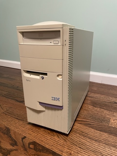
It came in a quite vintage and unique 90's case.
A beige CD-RW/DVD drive is shown here which is obviously not stock. The original CD drive did not want to read some of the disks I had burned, so I replaced it with this. Unfortunately this drive quit as well so I've since replaced it again.
While the exterior is beautiful, the case is removed in a rather violent way by grabbing the front and yanking it off. This seems to have killed the original IDE hard drive and a bargain bin replacement.
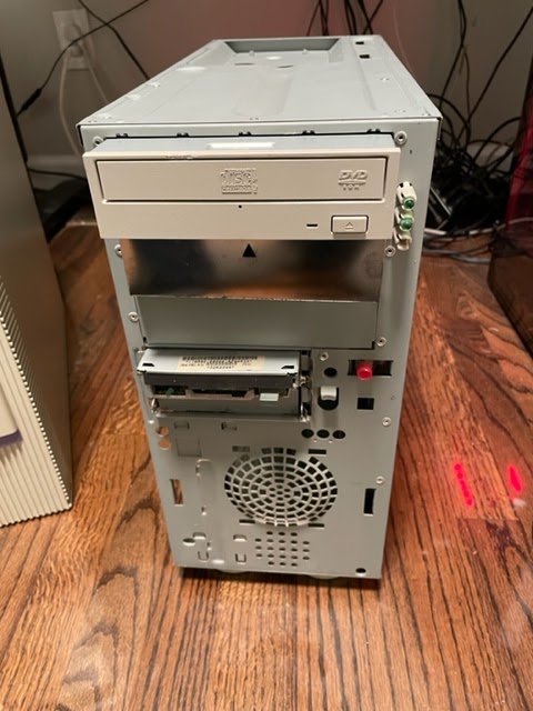 |
| Front case removed |
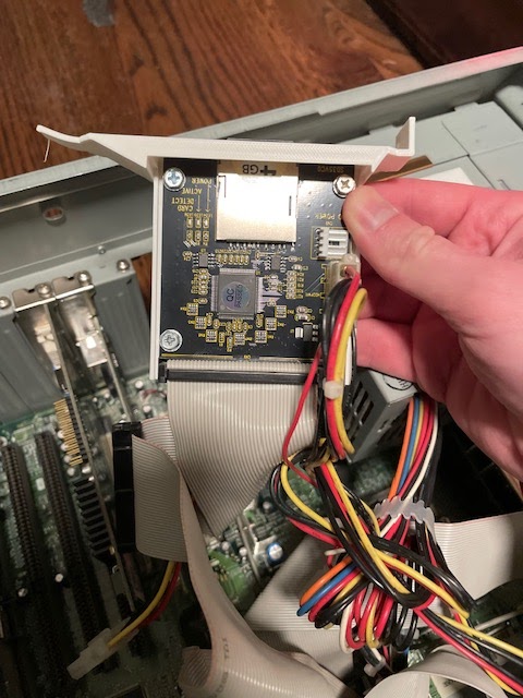
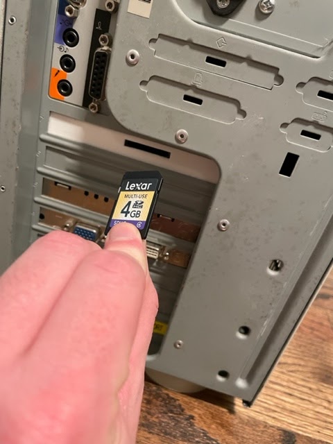
So I replaced the hard drive with a IDE to SD card adapter. This thing is great. You can swap out the SD card in the back, if you want to make backups, transfer files quickly or swap out operating systems. Using a design I found on Thingiverse, I 3D printed a bracket for it that works really well.

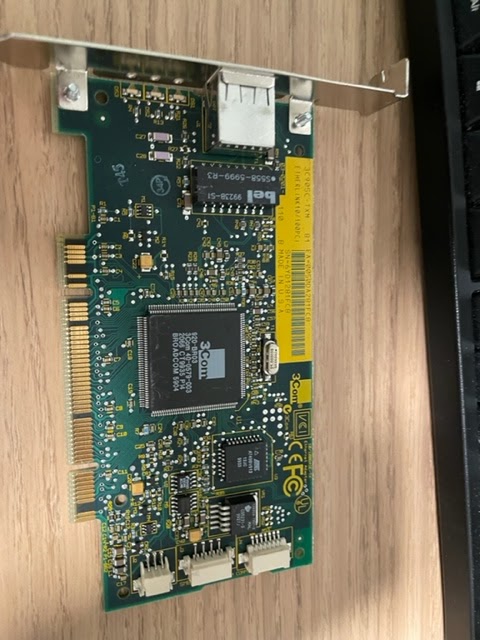
I also added this nice 3COM NIC from the late 90's.
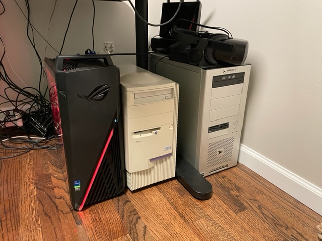 |
| Adding the PC to the huddle |
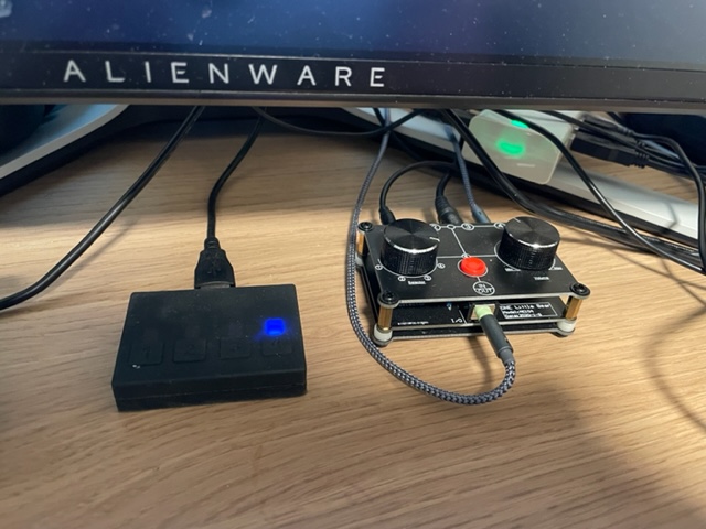
My KVM switch with an audio switch alongside
So I set about trying to get this old hardware working with my modern input and output. This was the most challenging part of the project.
The first challenge was the display, which was VGA only. I tried several cheap VGA to HDMI adapters all covered in this Vogons post with mixed and disappointing results. When in DOS mode, the VGA signal is 70hz, and all of the adapters I tried just tried to output 70hz to HDMI, which was not supported by my monitor.
I also snagged a Matrox G450 as a period-correct adapter with DVI input. Sadly the G450 had problems with EDID with my monitor when using DVI, but I decided to keep it anyway and to keep pursuing VGA.
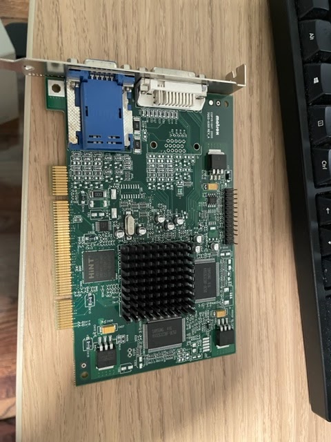 |
| Matrox G450 |
I finally landed on the Extron RGB-HDMI 300-A which almost did the job out of the box.
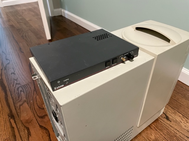
The one issue I had was again EDID. The Extron will pass this through HDMI by default which of course led to a broken 640x480 display in Windows. The Extron can also emulate EDID if you disable HDMI data, but the emulated 1920x1080 EDID wasn't honored by Windows - the best I could do was 1024x768. So I severed the EDID pins (#15 and #11) on my VGA cable and finally Windows stopped caring about what my monitor "supported". I was able to set a 1920x1080 resolution in Windows and now the whole thing works great.
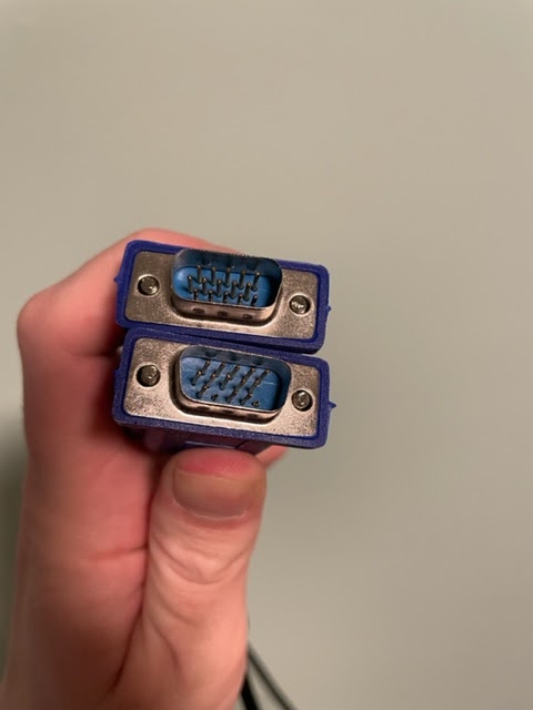 |
| VGA cable with the EDID pins severed |
Now on to the input. My KVM acts as a USB hub. I wouldn't be able to use the generic USB to PS2 adapters because I only have one USB connection coming from my USB KVM switch.
This computer does have USB ports, which work when you're logged on to Windows, but the
BIOS does not support HID devices, and I doubt DOS would either. I didn't want to have to grab another keyboard and mouse to use outside of Windows 98.
So I used an Arduino Uno with a Sainsmart USB Host shield to connect my keyboard and mouse. I used the ps2dev library to emulate the PS2 keyboard using GPIO pins. I tried doing this with the mouse but was unsuccessful. So I bought a TTL to RS232 adapter and use that to emulate a serial mouse.
My very rough Arduino sketch is here.
It took awhile to make this reliable but it works quite well now, with not too much lag.
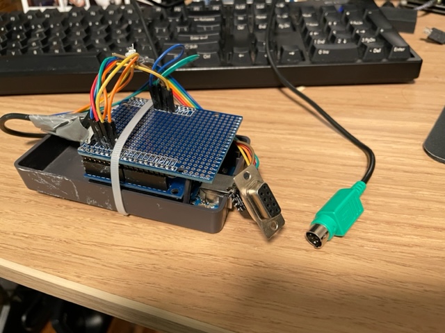 |
| The custom adapter with serial output for the mouse, and PS2 output for the keyboard. The top shield is just an Arduino proto shield so I could solder the PS2 and serial connections. |
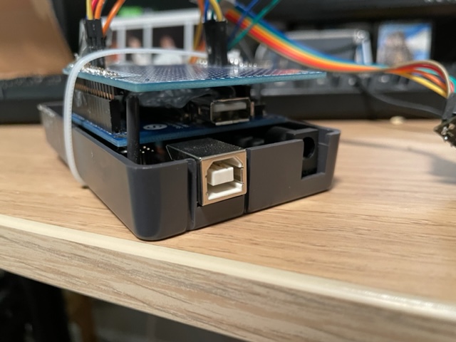 |
| USB input on the middle shield |
I named this PC "Little Blue" - after IBM's now sort of antiquated nickname of "Big Blue"
 |
| The bad ass boot logo |
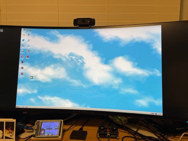
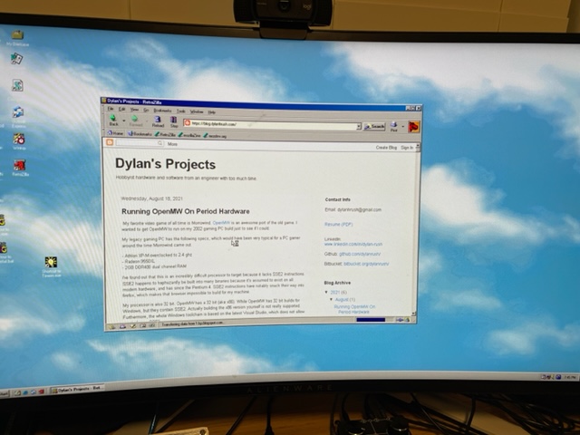 |
| Yes, it can browse the web using RetroZilla |
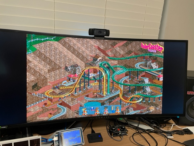 |
| Old school Roller Coaster Tycoon |
Wednesday, August 18, 2021
Running OpenMW On Period Hardware
My favorite video game of all time is Morrowind. OpenMW is an awesome port of the old game. I wanted to get OpenMW to run on my 2002 gaming PC build just to see if I could.
My legacy gaming PC has the following specs, which would have been very typical for a PC gamer around the time Morrowind came out.
- Athlon XP-M overclocked to 2.4 ghz
- Radeon 9550XL
- 2GB DDR400 dual channel RAM
I've found out that this is an incredibly difficult processor to target because it lacks SSE2 instructions. SSE2 happens to haphazardly be built into many binaries because it's assumed to exist on all modern hardware, and has since the Pentium 4. SSE2 instructions have notably snuck their way into firefox, which makes that browser impossible to build for my machine.
My processor is also 32 bit. OpenMW has a 32 bit (aka x86). While OpenMW has 32 bit builds for Windows, but they contain SSE2. Actually building the x86 version yourself is not really supported. Furthermore, the whole Windows toolchain is based on the latest Visual Studio, which does not allow you to forego SSE2.
Linux x86 binaries are no longer provided by the OpenMW team. Downloading the last x86 build, version 0.45, results in a segfault - probably due to missing SSE2 instructions again.
So I had to build OpenMW myself. I found a Gentoo package for OpenMW which would compile everything I needed. I decided to give Gentoo a shot because it might also let me compile my own compatible web browsers. This ended up being a very long process, as gentoo users are familiar with. I had to build and configure the whole operating from scratch, starting with the kernel.
I started up an i686 build of Gentoo in a virtual machine on my modern PC to be copied over to the old box after all the setup was complete. Compiling everything on the Athlon would likely take weeks.
After walking through the Gentoo installation manual I had a working terminal in 32 bits, but there were many snags on the way to a full desktop environment (xfce4).
The first snag was rustc. There are several packages which depend on rust. Rustc is a self-compiling compiler, which means it has to be bootstrapped. The rust compiler targeted for i686 contains SSE2 instructions, as described in gentoo bug 741708, which means that my Athlon could never bootstrap. I wanted to treat my VM like the physical machine so as not to run into any problems in the future, so I decided to compile rustc myself elsewhere then sideload the compatible binary.
My config.toml looks like this, which allows rustc to target either i586 or i686. In the end I ended up targeting i686 anyway (I think i586 broke librsvg) but it's good to have the i586 support. And this is compiled to match my instruction set.
changelog-seen = 2
[llvm]
cflags = "-march=\"athlon-4\" -m32"
cxxflags = "-march=\"athlon-4\" -m32"
ldflags = "-lz"
[build]
host = ["i586-unknown-linux-gnu", "i686-unknown-linux-gnu"] extended = true
configure-args = ['--build=i586-unknown-linux-gnu', '--prefix=/opt']
[install]
prefix = "/mnt/disk2/rust/install/opt"
[rust]
[target.x86_64-unknown-linux-gnu]
[dist]
I also had to avoid spidermonkey, which is not only a gargantuan thing to compile, but seemed to crash during compilation whether I used my sideloaded rustc or the one from dev-lang/rust-bin (I'm not even sure if rust caused the problem, but I had no interest in compiling spidermonkey. This reddit post helped me replace it with a more lightweight library (duktape)).
I also had to patch Qt5 to make it compatible with non-SSE2.
Eventually I was able to build xfce4 and OpenMW, and I was able to get in the OpenMW launch in my x86 VM:

This gave me hope that I could transfer the OS over to my old computer and get playing. Astonishingly, all I had to do was create a tarball of the root on my VM, and then extract that tarball to a new partition on my old PC. I just had to update the fstab and network config, run update-grub, and the operating system born in a VM was not running on a physical machine.
xfce didn't quite work though. The window manager crashes, so you lose window borders and close buttons. Luckily this didn't stop me from launching a terminal and eventually launching OpenMW.

I wasn't able to start the game from the main menu, but I could start the game from a random cell, which allowed me to start a new game from there.


Water was completely transparent.
It ran at about 2 FPS at 800x600. For comparison, the original Morrowind binary runs at around 30 FPS at around 1024x768. So not surprisingly, either OpenMW is just not optimized for my ancient hardware, or I could have some problem with my drivers.
Subscribe to:
Posts (Atom)